My new ShapeOko CNC router is up and going.
http://youtu.be/jqMCSxWVY4Y
Sunday, March 17, 2013


Sunday, December 16, 2012
Kossel Build Continues
The Kossel build continues. This is an easy build for sure if you already have a 3d printer. The parts for the top part of the frame were printed and assembled over Thanksgiving holiday. The leveling and calibration maybe where the real challenges are.
 I have been using AutoDesk 123D Design to create parts with. The effector and the rolling carriage were redesigned just because I wanted some CAD practice with the software and wanted some customized touches such as beveled hole entries and more mounting features. From OpenSCAD I exported the Kossel master files to an STL and then imported into SketchUp. From there I made measurements and dimensions that helped me get it into 123D Design.
 I had one redesign spin (so far) on the roller because I forgot the hole for the top endstop. In all the roller turned out great. The bearings are sitting very nicely centered on the flats. The roller uses 6 - 623 bearings. Three on each side. M3 screws are used all around with the exception of the string attachment which is is and M4. The four nuts that are used to pull the two halves together are nylocks.
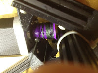 Once I had all three rollers assembled and installed I worked on the top part of the frame. I inserted the bearing into the line tensioners. At first it appeared to be too small to hold the bearing but I worked at it more and got it centered on the axial holes and it was fine. I inserted the plastic axel and the bearing spun freely. The tensioners and the axial were original Kossel designs.
 The rest of the top frame pieces went together without much trouble. Assembly method was similar to the bottom frame but easier since there was only a single frame to contend with. Keeping all screws about a turn from fastened so the frame pieces can move allowed for theme to come together.


Installing the fishing line was a bit fiddley but the time I did the last one i kind of got the hang of it. I printed the clamp and followed the method described in this video.
Fishing Line Install on Rostock Kossel using Clamp
For the most part the string does well winding and unwinding neatly. I'm not quiet sure of the tension needed. For now I will not worry about it as I will turn my attention on making the rods and attaching them to the effector
Santa will be bringing a Panucatt Azteeg_X3controller. I will be using an old ATX power supply from the old McWire to power it.

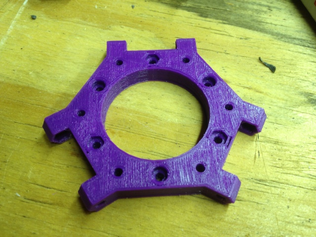 I have been using AutoDesk 123D Design to create parts with. The effector and the rolling carriage were redesigned just because I wanted some CAD practice with the software and wanted some customized touches such as beveled hole entries and more mounting features. From OpenSCAD I exported the Kossel master files to an STL and then imported into SketchUp. From there I made measurements and dimensions that helped me get it into 123D Design.


 The rest of the top frame pieces went together without much trouble. Assembly method was similar to the bottom frame but easier since there was only a single frame to contend with. Keeping all screws about a turn from fastened so the frame pieces can move allowed for theme to come together.


Installing the fishing line was a bit fiddley but the time I did the last one i kind of got the hang of it. I printed the clamp and followed the method described in this video.
Fishing Line Install on Rostock Kossel using Clamp
For the most part the string does well winding and unwinding neatly. I'm not quiet sure of the tension needed. For now I will not worry about it as I will turn my attention on making the rods and attaching them to the effector
Santa will be bringing a Panucatt Azteeg_X3controller. I will be using an old ATX power supply from the old McWire to power it.

Wednesday, November 28, 2012
New Project: Kossel
After seeing the Rostock DeltaBot in action I knew i had to have one. I orderded bearings, screws and nuts last week. So, i took advantage of Thanksgiving holiday/weekend and started printing parts.
At first I only printed one of the lower corner sets to see how it would fit together. The latest GitHub master had fixed alignment problems and everything fit well together.
My main tools for assembly were a 2.5mm ball end driver and some spring loaded tweezers. Forceps would work as well.
Here Re some instructions that go with included pictures. I am writing this with my phone and will have to make them inline later.
Instructions
 Populate these four hole locations of each frame_motor piece with 3 x 8 mm screws and jam nuts.
Attach each corner with two and M3 x 20 screws. All screws should be loose at this point.
 Slide the extrusion onto the loosen screws as shown.
Load the other two corners with screws and nuts.Work these in to the extrusions at the same time with the screws loose.
Slide in vertical extrusions.
Once together go around and firm up the screws.

You can test mount the motors with M3x8 screws. Using tweezers can really help with this step.
At first I only printed one of the lower corner sets to see how it would fit together. The latest GitHub master had fixed alignment problems and everything fit well together.
My main tools for assembly were a 2.5mm ball end driver and some spring loaded tweezers. Forceps would work as well.
Here Re some instructions that go with included pictures. I am writing this with my phone and will have to make them inline later.
Instructions
 Populate these four hole locations of each frame_motor piece with 3 x 8 mm screws and jam nuts.
Attach each corner with two and M3 x 20 screws. All screws should be loose at this point.

Load the other two corners with screws and nuts.Work these in to the extrusions at the same time with the screws loose.
Slide in vertical extrusions.
Once together go around and firm up the screws.

You can test mount the motors with M3x8 screws. Using tweezers can really help with this step.
Sunday, January 22, 2012
Drag and Drop Slic3ring
I am excited to see that Slic3r 0.6.0 is out!
Some new features of this new revision are:
When an STL file is drug and dropped on one of these, the batch file will launch Slic3r, load the configuration file and slice the STL. Theres not much feedback with Slic3r working in this mode. There is no GUI and you only know Slic3r is done when the command window says "Press any key to continue..." . I don't know if there is any warning if Slic3r had problems because I haven't had any yet.
Some new features of this new revision are:
- Thin walls
- New output file name format
- Option to create output file names using configuration option values
- Automatic retraction at the end of the print
The new naming option inspired me to write a batch file for drag & drop Slic3ring. It ended up to be pretty simple. Here's the setup I have at the moment.
On my desktop I have 3 batch files for 3 different print qualities:
draftSlic3r.bat
goodSlic3r.bat
bestSlicer.bat
Each batch file uses its own configuration file and has a customized output file format See the Slic3r readme for details.
Heres the contents of draftSlic3r.bat:
echo on
cd %~p0
C:\slic3r\slic3r.exe --load "C:\Documents and Settings\bjbsquared\My Documents\My Dropbox\slic3r_mosaic_draft.ini" %1
pause
When an STL file is drug and dropped on one of these, the batch file will launch Slic3r, load the configuration file and slice the STL. Theres not much feedback with Slic3r working in this mode. There is no GUI and you only know Slic3r is done when the command window says "Press any key to continue..." . I don't know if there is any warning if Slic3r had problems because I haven't had any yet.
Monday, December 26, 2011
Start and End Alterations
So now that I have all the minimum end-stops installed and working, I am able to do more automation and get closer to a "plug and play" print experience. I did this by changing some Skeinforge settings and adding code to the start.gmc and end.gmc files.
Skeinforge Adjustments:
I wanted to print in the middle of the bed so I activated Multiply and enter the bed's center coordinates.

If the names of the alteration files should be different than the default they can be change under the Skeinforge Preface tab.

Alteration Files
If you are using pronterface/sfact they should be here: ...\Pronterface\sfact_profiles\alterations\. If you are using only skeinforge they are here: ...\Pronterface\skeinforge\skeinforge_application\alterations\. My goal on writing these little snippets of g-code was to automate the things I have to do every time I print.
Right now I am using PLA and it tends to ooze out of the hot end between prints. So, before each print I want to prime the extruder. It seems to work best if it is primed in two steps with some delay in between. The extruder works on an absolute filament distance so, unless you know the current absolute distance, it needs to be reset in-order to move it a relative amount.
start.gmc
G92 E0 ;reset extruder position distance =0
G1 E10 ;Prime extruder
G28 ;Go Home ( woot! +1 for end-stops!)
G1 E20 ;Prime extruder 10mm more (10+10=20)
I am still tweaking this and it seems as it is never perfect but I enjoy the automation as it is still better than nothing.
Most of the things I print now are 1 each so at the end of each print I want the following:
Retract the extruder by 20mm to prevent ooze
Maneuver the platform to a place where the part can be taken off
Disable stepper so I can move axis by hand and also saves power
Turn off bed heater
Turn off extruder heater
Turn On Cooling Fan (set skein forge "Cooling" not to turn it off at end)
end.gmc
G92 E0 ; reset Extruder counter
G1 E-20 F900 ;Retract extuder 20mm at 900mm/min
G28 X0 Y0 ;Go Home but keep Z height
G92 X0 Y0 Z0 E0 ;reset all locations and extruder
G1 Y80 F3000.0 ; Move platform so part can be removed
M84 ;disable steppers so they dont get hot during idling
M140 S0 ;turn off bed heater
M104 S0 ;turn off extruder heater
M106 S255 ; Turn on cooling fan
To make sure the code is going to be used, the g-code can be examined in a text editor. After skeining, the g-code is in the same directory as the yourPart.stl file. There are two versions. The yourPart_penultimate.gcode version is the one with the comments and is easier to read . The Alteration code should be included and wrapped in <alteration> tags. Such as:
(<alteration>)
G92 E0 ;reset extruder position
G1 E10 ;Prime extruder
G28 ;Go Home
G1 E20 ;Prime extruder
(</alteration>)
The start.gmc and end.gmc should be at the start end of the file as expected. If not make sure the files are in the proper directory(SFACT uses same directory names) and the files are named properly.
Subscribe to:
Posts (Atom)