Saturday, April 20, 2013

rev:Alpha Meter, Meter Panel Eater

Ok, stupid title but sometimes thou gotta let one out.

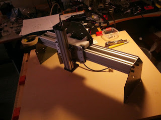
Anyway, here  rev:Alpha of my ShapeOko upgrade on GitHub.

Overview

Overview
In general I think I have met all my design goals. The only compromise was the over all size. At one time I did experiment with what overall size it would take just to load in a 24"x24" panel. The savings did not justify the effort of trimming down the extrusion nor the wood. Leaving the extrusion  at 1 meter and foot print 48"x48", the cutting area is about 40"x31".
So size was a compromise but I have room for it and I think this space will be worth it. Unlike other things in my garage this will "pay rent".  I may have to do some spring cleaning and  "evict" some junk to find this a home.

X-Rail and Gantry Improvements

X Gantry Box like design
Because of the noticeable give in my current ShapeOkos gantry I really wanted to solidify the X rail and carriage. I scanned the forums and extracted what I thought was the best ideas for doing so.  The upgrade are:

Double X-rails witwlanfox Blocks  - It was pretty much a consensus that a Double-X rail would be needed for the meter span. I also thought that the wlanfox Blocks  were an excellent idea and be made of 3/4" plywood. I will use M5 threaded rod and nylock nuts to span the distance of the blocks. I think using nylock nuts all around is a good idea as I have had some nuts loosen and fall off  in the middle of a job. Also 4 more V-Wheel Kits are needed.
Gantry Underside

Standard Wheel Carriage Plate - Using these instead of the existing motor plate lowers the X-Rail so that the resulting moment arm is reduced. Forces in the Y direction should have less twisting effect on the Gantry and X-Rail assembly. The draw back of this mod is that the Y motors have to be relocated.  You can see in the overview picture that they will be mounted on a fabricated item I call the Motor-Buttress assembly (blue).  This will require longer timing belts and two additional Smooth Idler Wheel Kits.
Standard Wheel Carrage Plate


 Part Fabrication

Idler Butress Assembly
I will use the ShapeOko to cutout the parts to make the Idler and Motor Buttress Assemblies as well as the wlanfox Blocks. I'm hopeful that I get it right before I tear down the ShapeOko for upgrading. If not then I will have to resort to my skills with hand tools which will be a big time suck and an exercise of patience but we will getr done.


Saturday, April 13, 2013

ShapeOko : The next step

So I have been running jobs on my ShapeOko cnc mill for a few weeks now.  I think I know where I want to take the upgrades.

These are in no particular order.

Up Sizing

The cutting area I have now is roughly 8x8 inches. A standard plywood Hobby Panel from a hardware depot store is 24"x24 inches. I think I would be using these in various thicknesses for the majority of the projects I will be doing.  The  Maker slide extrusion only comes in 200, 375, 1000 and 1800mm. This translates into 8, 15, 39 and 71 inches.  Not a lot of choices here. The closest size for my use is 1000mm.  When I consider the extra space needed for the machine the overall size is going to be roughly 48x48 inches. About a half sheet of plywood. This is a bit bigger foot print  than I wanted but I can't bring myself to cut down the extrusion. It would just seem like a waste of money.

Mitigate Y Lag

wlanfox great ideal to add blocks to stiffen carriage.
On my machine there is  a very noticeable Y lag that is evident in the oval holes created.  This is happening mainly because of 2 reasons:


  1. Probably the biggest  and clearest shortcoming of the ShapeOko is the unpowered Y rail. I will be going to a 2 motor configuration.
  2. The carriage stiffness needs to be improved. I will be doubling the X rail and using wlanfoxBlocks to stiffen the X carriage assembly.


Another Idea I had was to lower the X rails so the moment arm against them is not so big.  This would be limiting to the Z range but might be worth it.

Spindle

In a sense I have already upgraded my spindle. I have replaced it with my 15yr old dremel tool. This is because the rotatory tool that came with the machine would not hold the bits in reliably. There is a push button on the rotary tool that is used to stop the chuck from moving while it is being tightened. The button is unable to resist the pressure given when tightening and the chuck skips past the stop for some reason.

The spindle caused milling failures twice by releasing the bit mid-run.  On the second time I cut the cord off and threw it in the trash. I figured I could use the cord on a project and no one should use this tool in this dangerous condition.

I'm thinking that the DW660 would suit my needs. It seems like the bigger brother of the Dremel tool I have now. I will have to research this further but for now, this is my target.


Sunday, March 17, 2013

My new ShapeOko CNC router is up and going.

 http://youtu.be/jqMCSxWVY4Y

Sunday, December 16, 2012

Kossel Build Continues

The Kossel build continues. This is an easy build for sure if you already have a 3d printer. The parts for the top part of the frame were printed and assembled over Thanksgiving holiday. The leveling and calibration maybe where the real challenges are.

I have been using AutoDesk 123D Design to create parts with. The effector and the rolling carriage were redesigned just because I wanted some CAD practice with the software and wanted some customized touches such as beveled hole entries  and more mounting features. From OpenSCAD I exported the Kossel master files to an STL and then imported into SketchUp. From there I made measurements and dimensions that helped me get it into 123D Design.


I had one redesign spin (so far) on the roller because I forgot the hole for the top endstop. In all the roller turned out great. The bearings are sitting very nicely centered on the flats.  The roller uses 6 - 623 bearings. Three on each side.  M3 screws are used all around with the exception of the string attachment which is is and M4. The four nuts that are used to pull the two halves together are nylocks.


Once I had all three rollers assembled and installed I worked on the top part of the frame.  I inserted the bearing into the line tensioners. At first it appeared to be too small to hold the bearing but I worked at it more and got it centered on the axial holes and it was fine. I inserted the plastic axel and the bearing spun freely. The tensioners and the axial were original Kossel designs.

The rest of the top frame pieces went together without much trouble. Assembly method was similar to the bottom frame but easier since there was only a single frame to contend with. Keeping all screws about a turn from fastened so the frame pieces can move allowed for theme to come together.


Installing the fishing line was a bit fiddley but the time I did the last one i kind of got the hang of it. I printed the clamp and followed the method described in this video.
Fishing Line Install on Rostock Kossel using Clamp


For the most part the string does well winding and unwinding neatly. I'm not quiet sure of the tension needed. For now I will not worry about it as I will turn my attention on making the rods and attaching them to the effector


Santa will be bringing a Panucatt Azteeg_X3controller. I will be using an old ATX power supply from the old McWire to power it.

Wednesday, November 28, 2012

New Project: Kossel

After seeing the Rostock DeltaBot in action I knew i had to have one. I orderded bearings, screws and nuts last week. So, i took advantage of Thanksgiving holiday/weekend and started printing parts.

At first I only printed one of the lower corner sets to see how it would fit together. The latest GitHub master had fixed alignment problems and everything fit well together.

My main tools for assembly were a 2.5mm ball end driver and some spring loaded tweezers. Forceps would work as well.
Here Re some instructions that go with included pictures. I am writing this with my phone and will have to make them inline later.

Instructions

Populate these four hole locations of each frame_motor piece with 3 x 8 mm screws and jam nuts.
Attach each corner with two and M3 x 20 screws. All screws should be loose at this point.


Slide the extrusion onto the loosen screws as shown.

Load the other two corners with screws and nuts.Work these in to the extrusions at the same time with the screws loose.


Slide in vertical extrusions.
Once together go around and firm up the screws.


You can test mount the motors with M3x8 screws. Using tweezers can really help with this step.